Procedural generation is one of my favorite topics. There is a very particular aesthetic in writing seemingly simple rules from which emerge complex structures. However, this complexity also means dealing with millions of data points, which often times result in very slow procedures. Fortunately, in many instances it is possible to heavily parallelize these algorithms. So come with me and let’s explore world generation using shaders!
The task we’ll tackle is generating a tropical island completely procedural. I have not created any 3D asset yet (vegetation, buildings, rocks…) so we’ll concentrate on the base terrain itself. Once it is generated, with biomes and everything, it should be fairly straightforward to scatter these assets using a Poisson disc sampling algorithm or similar technique. But that’s for another day.
But before diving into the generation itself, one may wonder why we would want to walk the difficult route of procedural terrain generation. I mean, beside the obvious cool factor, this is much more complex than authoring 3D models my hand, with less control over the actual output. To answer this question I’ll describe a bit the project. I am making a game prototype of a multiplayer competitive crafting and fighting game, where each player tries to create the tools required to retrieve some form of treasure before the other do. Now because part of the game loop is having to find scarce resources, the game would have very little replayability if we were to author one map, as players would be spoiled of the thrill to find them. And that’s really where procedural generation shines. It allows spicing up things by introducing an element of randomness, in an organic fashion. My two cents is, it is always best to make remarkable landmarks by hand, and avoid procedural generation if it can be avoided. But should there be a need for infinite content and replayability, this is the only strategy.
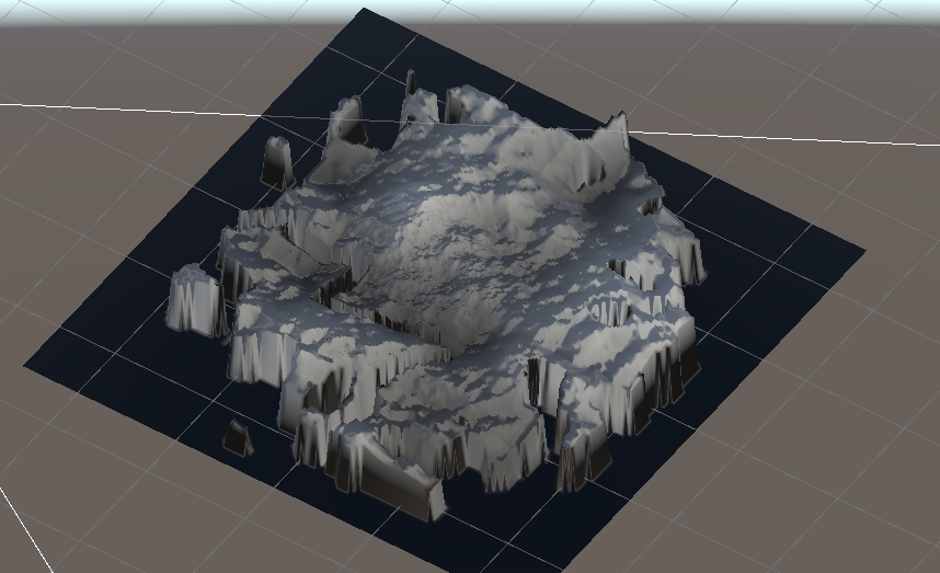
So here’s the plan: we are going to generate a grid of points, which will correspond to the vertices of the mesh. Using some structured noise function, we will assign a height to each point. Then we will use a remapping function to give some characteristics to the terrain topology, like sharp cliffs or such. At this stage we will have a base terrain. With this out of the way, we can then generate the shape of our island. We then compute a distance function to the coast and modulate the terrain’s height based on these. Lastly, we generate some biomes based on the height, the distance to the coast and some extra noise function, and we then blend together several terrains with various remapping functions to obtain our final terrain. The goal of this last step is to add some variety to the island topography.
I have done something very similar in this project in Unreal Engine 4, but it was somewhat limited in resolution because everything was generated on CPU. The whole motivator for this new project is really to get everything running in shaders and that’s what we’ll do!
As a side note, I made the stylistic decision to level the terrain in this older project, having discrete possible elevations. And while very nice looking in my opinion, this made traversing the terrain tedious. And the generation process was quite different as it required the ability to generate truly vertical planes. In the point grid approach described in the previous paragraph, this would require an infinite grid resolution, so we’ll stay away from leveling the terrain for now.
I find that when doing procedural things it is easier to use unity, so that’s what we’ll do. Everything will be done inside compute shaders and their accompanying C# scripts. You can follow along he
A few good references
I think it is important to give credit where credit is due. So I would definitely recommend checking out Sebastian Lague’s Youtube channel and Simon Dev’s. I also found this video from Jonas Tyroller on procedural island generation very inspiring, even though it uses very different techniques.
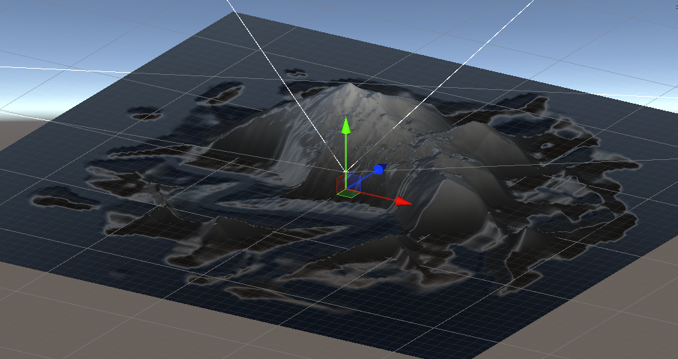
The base terrain
As a starting point we use a grid of point which represent the vertices of a subdivided plane. This will indeed limit our ability to terrain that curls back onto itself like caves, or vertical planes, but in most instances this is sufficient, given we have no plan on adding underground structures. And should we want to make steeper cliffs, we can either increase the grid resolution, or add hand-authored meshes on top of the base terrain mesh. On the other hand, this allows for a very lightweight data structure as the only dynamic parameter of our terrain is the height of each vertex.
We therefore represent the data a ComputeBuffer of floats:
ComputeBuffer heightMap = new ComputeBuffer(resolution * resolution, sizeof(float));
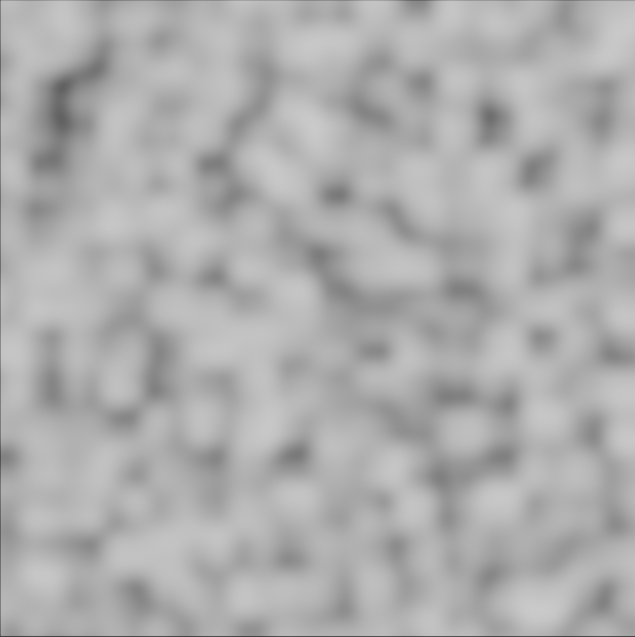
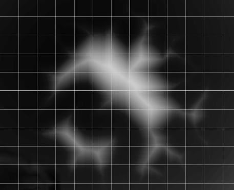
The very first step is to generate the height for each vertex using some gradient noise function such as Perlin Noise. Gradient noise has the interest, as compared to completely random values, to retain some sort of structure, just like real terrain. I further used a fractal noise. This is to say that I layered several octaves of noise, each with a different frequency and amplitude. This is a very common technique in procedural generation, as it allows adding details at different scales. Below is a comparison of perlin noise with only one “octave” and several “octaves”:

Altogether the shader code looks like this:
#pragma kernel HeightMap

#define THREAD_GROUP_SIZE 64

RWStructuredBuffer<float> heightMap;

// base noise params
int octaves = 1; // how many layers of noise
float scale = 5.0f; // base frequency
float lacunarity = 2.0f; // how fast the noise freq grows
float persistence = 0.5f; // how fast the noise decays
float seed = 0.0f;

[numthreads(THREAD_GROUP_SIZE, 1, 1)]
void HeightMap (uint3 id : SV_DispatchThreadID)
{
    float2 coord = getCoordsWithOffset(id.x, size, offset, zoom);
    float value = 0;

    float amplitude = 1.0;
    float totScale = scale;
    float totAmp = 0.0;
    for (int i = 0; i < octaves; i++) {
        totAmp += amplitude;
        value += noise(coord * totScale, seed) * amplitude;
        amplitude *= persistence;
        totScale *= lacunarity;
    }

    heightMap[id.x] = value / totAmp * maxHeight;
}


// 2D Noise based on Morgan McGuire @morgan3d
// https://www.shadertoy.com/view/4dS3Wd
float random (float2 id, float seed) {
    // float3 p3 = frac(float3(id.xy, id.x) * 0.13);
    // p3 += dot(p3 + seed, p3.yzx + 3.333);
    // return frac((p3.x + p3.y) * p3.z);
    return frac(
        sin(dot(id.xy, float2(12.9898,78.233))) * (43758.5453123 + seed));
}


float noise (float2 id, float seed) {
    float2 i = floor(id);
    float2 f = frac(id);

    // Four corners in 2D of a tile
    float a = random(i, seed);
    float b = random(i + float2(1.0, 0.0), seed);
    float c = random(i + float2(0.0, 1.0), seed);
    float d = random(i + float2(1.0, 1.0), seed);

    // Smooth Interpolation

    // Cubic Hermine Curve.  Same as SmoothStep()
    float2 u = f * f * (3.0 - 2.0 * f);

    // Mix 4 coorners percentages
    return (lerp(a, b, u.x) +
            (c - a) * u.y * (1.0 - u.x) +
            (d - b) * u.x * u.y);
}
There are few interesting things happening here. First things first, the main kernel runs on a one-dimensional array. Obviously, our grid of points is 2D. So we will have to convert, most of the time, the 1D coordinates (the input of the kernel) to a 2D position in the real world to query the appropriate attributes. However, the same would have been true if we had used 2D coordinates as input: ultimately, given the ComputeBuffer holding the heights is 1D, and thus we would have had to convert the 2D coordinates to 1D to write the height value. So it is really a matter of preference.
There also is a getCoordsWithOffset function call at the start of the kernel. We will come back later to what it actually does, but essentially it returns the x and y coordinates of the vertex from its 1D index.
Lastly, the random function is actually a pseudo random number generated based off some coordinates and a seed. The original implementation did not have a seed, but this is important in our application, to be able to generate various terrains.
Also, I use a THREAD_GROUP_SIZE of 64, but this could be adapted to the hardware. I wrote this kernel on an older laptop with a GTX 1060, so chose smaller resolutions and group sizes, but more recent GPUs with more VRAM and cores could sere better throughput with larger group sizes possibly. One would need to benchmark.
My laptop is choking 🙀
Let’s imagine an ideal world where there is infinite compute. In this context, the perfect generation algorithm would simulate such fine details that the player could see the small pebbles. But realistically, on consumer grade hardware, it would not be possible to simulate such terrain in real time. So we need to find a way to reduce the amount of computation required to generate the terrain. Usually, the first optimization trick is to try to not allocate as many resources to in-game objects that are not visible.
Typically, this can be translated into 2 things: culling and level-of-details. Culling is the act of not showing and/or rendering objects that are not visible to the camera. In our case we will use a third person camera, so we cannot rely on this technique as we may actually see quite a large field of view. Also given we are dealing with the terrain, with large structures, culling entire chunks of terrain may result in incorrect shadow customs. So we will not use culling.
Level-of-details however is a good idea. As objects move away from the camera, more than one triangle that composes the object’s mesh might end up inside a single pixel of the screen. This means that we probably don’t need both these triangles. As we move away from the camera, we may therefore progressively replace the mesh with less detailed versions, or, alternatively re-mesh the object such that each pixel basically contains one triangle. In our case what we can do is subdivide the terrain in chunks of various spatial resolution, as they get further away from the camera.
In practice, what we do is divide the space into a quad-tree. The world (or level) is subdivided into 4 quadrants. Each quadrant is further subdivided into 4 if its center is less than one quadrant size away from the player, and so-on until a maximum recursion size.
The point of doing it this way (as opposed to having a single grid of variable local resolution) is that each chunk now has a constant vertex spacing, and we also keep a constant number of vertices across chunks, which makes it easier to deal with in the shader kernels.
Now this yields two extra issues to deal with. First, given we use the same kernel for all chunks, we need to account for the tile offset and “zoom”, that is the spacing between the vertex, and thus its overall size. This is what the getCoordsWithOffset function actually does:
float2 getCoordsWithOffset(
        uint id, int bufferSize, float2 position, float zoomLevel) {
    int2 uvs = int2(floor(id / bufferSize) - 1, id % bufferSize - 1);
    float2 coords = float2(uvs) / (float(bufferSize) - 3.0f);
    return coords / zoomLevel + position;
}
The second issue is occurs at the edge of 2 chunks of different resolution. Every other vertex of the higher resolution chunk will match one of the lower resolution one. But the other vertices will not, and depending on the noise function value at these vertices, they might not line up with the low resolution chunk edge. So instead, what we do is, for these vertices, we compute the position on the edge they should have to match the edge.
Hopefully, with the right base resolution, the result is seamless for the player.
Something new (?)
Up to this point, everything I have described could have been found in one form or another in some other tutorials. But now we get to the fun bit, for which I actually needed to use a bit more brain juice. We currently have a terrain that covers the entire map. But what we want is an island in the middle of the sea. For practical reasons, we also need this island to be centered on the map.
To do this we can start by drawing the shape of the island. At the highest level, it basically is a deformed circle. So what we can do is for each point on the grid compute whether the point is within a given radius from the center of the grid, plus or minus some random value. Again we use some gradient noise for continuity.
My initial idea was to use polar coordinates. This way we could ensure having the same noise value for all the grid points that share a common angle in polar coordinates. This would also mean that the noise function we use would need to be periodic of period 2 pi to ensure continuity.
Upon experimenting, however, I found that using regular cartesian coordinates would lead to a more organic island shape, we possibly some “rock” formations outside the main island, which looks really cool and natural. Below is a comparison of both methods, with polar coordinates first:
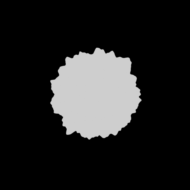
Designing a kernel which follows the above principles we can get a binary mask for where the island should be:
[numthreads(THREAD_GROUP_SIZE, 1, 1)]
void MakeIslandMask(uint3 id : SV_DispatchThreadID)
{
    float2 coord = getCoords(id.x, waterMaskSize, float2(0.0f, 0.0f), 1.0f);
    coord -= 0.5;
    float len = length(coord);
    float dist = len * 2;
    float threshold = (
        1 - noise(coord * islandNoiseScale, seed) * (1 - islandRoundness));
    waterMask[id.x] = step(threshold, dist);
}
Now, we cannot simply multiply the terrain height with the mask. This would lead to obvious discontinuities, which barely ever occur in real life. What would instead make sense would be to have the terrain height gradually decrease as it gets closer to the sea shore.
What we therefore need to know is the distance to the coast. Starting from the binary island mask, we can compute a 2d euclidean distance transform. Because everything occurs inside a shader, we ideally want the algorithm to be fairly straightforward and highly parallel. So what I ended up doing is repeatedly calling the same kernel, which propagates the distance to the closest coast. The kernel is called until the distance transform converges. This is not the most efficient algorithm, but it is simple and works well enough for our purposes.
RWStructuredBuffer<float> mask;
RWStructuredBuffer<float> distanceFieldIn;
RWStructuredBuffer<float> distanceFieldOut;
int size;

int getDist(uint idx, float minDist, int dist, out bool shouldBreak) {
    if (mask[idx] > 0.5) {
        shouldBreak = true;
        return min(minDist, dist);
    }
    if (distanceFieldIn[idx] < size) {
        shouldBreak = true;
        return min(minDist, distanceFieldIn[idx] + 1);
    }

    shouldBreak = false;
    return minDist;
}

[numthreads(THREAD_GROUP_SIZE, 1, 1)]
void ComputeEDT (uint3 id : SV_DispatchThreadID)
{
    if (mask[id.x] > 0.5) {
        distanceFieldOut[id.x] = 0;
        return;
    }

    int2 pos = int2(floor(id.x / size), id.x % size);
    float minDist = distanceFieldIn[id.x];
    bool shouldBreak = false;

    // for each succesive i-th order neighbour, if neighbour already knows its
    // distance to the coast, compare it to current known distance to coast,
    // and store smallest.
    for (int i = 1; i < size; i++) {
        if (pos.x - i >= 0) {
            minDist = getDist(id.x - i * size, minDist, i, shouldBreak);
        }
        if (pos.x + i < size ) {
            minDist = getDist(id.x + i * size, minDist, i, shouldBreak);
        }
        if (pos.y - i >= 0) {
            minDist = getDist(id.x - i, minDist, i, shouldBreak);
        }
        if (pos.y + i < size) {
            minDist = getDist(id.x + i, minDist, i, shouldBreak);
        }
        if (shouldBreak) {
            break;
        }
    }

    distanceFieldOut[id.x] = minDist;
}
You’ll notice that the offset we had for the height map is not present. This is because, we are going to generate this map only once when loading the level and then sample it upon re-generating a terrain chunk. This makes things much faster as the above kernel might run up to once for each off the points on one axis of grid.
Below is a picture of the computed distance field:
With the distance to the coast computed, we can simply multiply the terrain height with this distance, normalized by the maximum distance to the coast.
More water
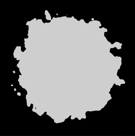
For gameplay reasons, I felt it’d be interesting to split the island in two parts with a large river of sort, creating 2 separate play areas. So what I did was to randomly select two sides of the map. Then we create a virtual quadratic Bézier curve that goes through the center of both sides, and the center of the map. Now, inside a kernel, we can compute for each point the distance to the curve like so:
float DistanceToQuadraticBezier(float2 pos, int maskSize)
{
    float minDist = maskSize * maskSize;
    for (int t = 0; t < 100; t++) {
        float interp = float(t) / 100.0f;
        float2 a = lerp(start, center, interp);
        float2 b = lerp(center, end, interp);
        float2 val = lerp(a, b, interp);
        val += noise(val * riverNoiseScale, seed) * riverNoiseAmount;
        float dist = length(val - pos);
        if (dist < minDist) {
            minDist = dist;
        }
    }

    return minDist;
}
This is indeed a very brute force approach. I sampled 100 points along the curve and for each of the grid points selected the closest one as the grid point’s projection on the curve. There is most likely some cool math derivation to compute the projection of a point on a quadratic Bézier curve, but I honestly got lazy, and this works well enough for the first version. Premature optimization is rarely a good thing. I will of course revisit this code one day if I need to get the generation faster. But at this stage the entire generation process runs in less than 2s which is more than acceptable for something that only runs once at loading time.
Either way, I then used this distance to alter the previous distance field to the coast, like so:
[numthreads(THREAD_GROUP_SIZE, 1, 1)]
void GenerateRiver (uint3 id : SV_DispatchThreadID)
{
    float2 coords = getCoords(id.x, waterMaskSize, float2(0.0f, 0.0f), 1.0f);

    waterMask[id.x] = (
        1
        - step(riverWidth, DistanceToQuadraticBezier(coords, waterMaskSize))
        * (1 - waterMask[id.x])
    );
}
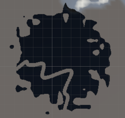
Overall, I am quite happy with the result, as, besides the practical gameplay aspect, it gives a more unique look to the island. Below, in black is the final water mask:
Biomes
Up to this point we have only ever used a single noise function. However, base Perlin noise in itself is quite dull, monotonous. In the real world, depending on the region, the gradient of the terrain should be more or less steep, and the maximum height delta could vary a lot. A plain will barely have any variation, while a mountain will have a lot. And even among mountain chains, some have steep peaks like the Alps and Himalaya, while others have a lot of plateaus like the Andes. So we need to find a way to add some variety to the terrain.
The first thing to do is does to impose some character to the noise. This is done using a remapping function. For making it easy to control for an artist, I used an animation curve in Unity, that I then resample. Inside the shader kernel I then linearly interpolate inside the sampled point array to map each previously generated height to the desired one:
StructuredBuffer<float> shapingFunction;

float shapeLerp(float x) {
    int idx = int(max(min(x * 100.0f, 99.0f), 0.0f));
    int plusone = min(idx + 1, 99);

    float a = shapingFunction[idx];
    float b = shapingFunction[plusone];
    return lerp(a, b, frac(x * 100.0f));
}

[numthreads(THREAD_GROUP_SIZE, 1, 1)]
void ApplyShapingFunction(uint3 id : SV_DispatchThreadID) {
    heightMap[id.x] = shapeLerp(heightMap[id.x] / maxHeight) * maxHeight;
}
The shaping function itself is defined as follows in unity C#:
public AnimationCurve heightCurve = AnimationCurve.Linear(0, 0, 1, 1);

...

void ConvertShapingCurveToArray(
        ref AnimationCurve heightCurve, out float[] shapingFunction) {
    shapingFunction = new float[100];
    for (int i = 0; i < 100; i++) {
        shapingFunction[i] = heightCurve.Evaluate(
            (float)i / (float)100.0f);
    }
}

...


float[] shapingFunction;
ConvertShapingCurveToArray(
    ref heightCurve, out shapingFunction);
var shapingBuffer = new ComputeBuffer(
    shapingFunction.Length, sizeof(float));
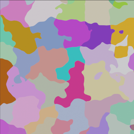
Now that we have the ability to generate more unique terrains, what we want is to mix and match them. To do so, we take a grid of a set resolution, with each cell having its index assigned as value. This represents our various biomes.
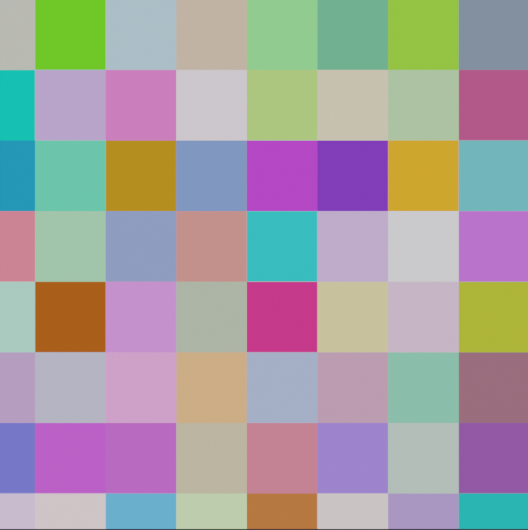
Now we generate a second grid that we deform using some Perlin noise, and we sample the cell of the original grid in which each point lands. What results is a patchwork of organic looking regions, all connected, with one biome assigned to each. The last step is to remap each region’s biome to the corresponding biome, using a modulo operator, where the modulo is the number of desired biomes.
RWStructuredBuffer<float2> points;

int numPoints = 10;
float seed = 0.0f;
float gridDistortion = 1.0f;


// buffer for the closest point to any given pixel
RWStructuredBuffer<int> closestPoint;
// distance to the closest point
RWStructuredBuffer<float> distanceToCenter;
// Idx of the property assigned to each element of the buffer
RWStructuredBuffer<int> regions;
int size = 512; // width of a map
float zoom = 1.0f;
float2 offset = float2(0.0f, 0.0f);

// number of properties to assign to regions
uint numProperties = 4;
float samplerNoiseFreq = 30.0f;
float samplerNoiseFactor = 0.1f;

// buffers for the masks
RWStructuredBuffer<float> mask; // buffer of size * size * numProperties. We use
                                // floats as buffers must have a stride that is
                                // a multiple of 4 which excludes bools and
                                // float will make it easier to blur


// Sample a grid of points, then displace them by a noise function.
// While this will not guarantee that the points are at least a given distance
// away from each other, it does maintain a grid like structure for fast queries
[numthreads(THREAD_GROUP_SIZE, 1, 1)]
void DisplacedGridSampler (uint3 id : SV_DispatchThreadID)
{
    if (id.x >= uint(numPoints * numPoints)) {
        return;
    }

    float spacing = 1.0f / float(numPoints);
    float remainder = spacing * 0.5f;

    // compute the coordinates of the point
    uint2 uv = uint2(id.x / numPoints, id.x % numPoints);
    float2 coords = float2(uv) * spacing + remainder / 2.0f;

    // displace the point
    float noiseVal = random1D(seed + id.x);
    float2 direction = float2(
        cos(noiseVal * 10 * 3.14159 + 18.3564),
        sin(noiseVal * 10 * 3.14159 + 18.3564)
    );
    float amplitude = random1D(noiseVal);
    float2 displacedCoords = (
        coords + direction * amplitude * spacing * 0.5f * gridDistortion);

    points[id.x] = displacedCoords;
}


[numthreads(THREAD_GROUP_SIZE, 1, 1)]
void ClosestPointOnDisplacedGrid (uint3 id : SV_DispatchThreadID)
{
    float2 coords = getCoordsWithOffset(id.x, size, offset, zoom);
    coords = clamp(coords, 0.0f, 1.0f);

    float spacing = 1.0f / float(numPoints);

    // retrieve all the possible grid points in a viscinity given the
    // coordinates of the pixel
    int2 gridCoords = int2(floor(coords / spacing));

    // we displace the point to get a noisier boundary
    float noiseVal = noise(coords * samplerNoiseFreq, seed);
    float2 direction = float2(
        cos(noiseVal * 3.14159 + 18.3564),
        sin(noiseVal * 3.14159 + 18.3564)
    );
    coords += direction * noiseVal * spacing * samplerNoiseFactor;

    // compute the distance to each point
    float minDist = 10000.0f;
    int closest = -1;
    for (int i = -1; i < 2; i++) {
        if (gridCoords.x + i < 0 || gridCoords.x + i >= numPoints) {
            continue;
        }
        for (int j = -1; j < 2; j++) {
            if (gridCoords.y + j < 0 || gridCoords.y + j >= numPoints) {
                continue;
            }
            int idx = (gridCoords.x + i) * numPoints + gridCoords.y + j;
            float d = distance(
                coords,
                points[idx]
            );
            if (d < minDist) {
                minDist = d;
                closest = idx;
            }
        }
    }

    closestPoint[id.x] = closest;
    distanceToCenter[id.x] = minDist;
    regions[id.x] = uint(
        floor(random1D(seed + float(closest)) * numProperties));
}
Generating the final terrain
Given the height map, we run a simple compute shader to retrieve the terrain chunk’s mesh, UV coordinates, normals and texture. Then we apply it using C# code. There are ways to manipulate the mesh directly inside the shader but provided we also need the mesh for computing collisions with the player, I found it was easier this, albeit probably a bit slower.
The shader code:
struct Vertex{
    float3 position;
    float2 uv;
    float3 normal;
};

RWStructuredBuffer<float> heightMap;
RWStructuredBuffer<Vertex> vertices;
RWStructuredBuffer<int> tris;

uint size;
uint width;

void ComputeNormal(uint heightId, uint vtxId, float offset = 1.0f) {
    // get vertices surrounding the current vtx
    float3 p1 = float3(0, heightMap[heightId], 0);
    float3 p2 = float3(0, heightMap[heightId + size], offset);
    float3 p3 = float3(0, heightMap[heightId - size], -offset);
    float3 p4 = float3(offset, heightMap[heightId + 1], 0);
    float3 p5 = float3(-offset, heightMap[heightId - 1], 0);

    // compute edges
    float3 e1 = p2 - p1; // up
    float3 e2 = p3 - p1; // down
    float3 e3 = p4 - p1; // right
    float3 e4 = p5 - p1; // left

    // compute normals
    float3 normal = float3(0, 0, 0);
    normal += cross(e3, e1);
    normal += cross(e1, e4);
    normal += cross(e4, e2);
    normal += cross(e2, e3);

    // normalize
    vertices[vtxId].normal = normalize(normal);
}

void SetVertex(uint vtxId, uint heighIdx, float2 coord, int bufferSize){
    coord /= float(bufferSize - 1);
    vertices[vtxId].uv = coord;
    vertices[vtxId].position = float3(coord.x * width - width * 0.5f,
                                      heightMap[heighIdx],
                                      coord.y * width - width * 0.5f);
    ComputeNormal(heighIdx, vtxId, 1.0f / float(bufferSize + 1));
}

void CreateVertex(uint3 id) {
    uint2 coord = uint2(floor(id.x / size), id.x % size);

    // don't create vertices on the first and last column and rows
    // because these are only used for normals calculation
    if (
        coord.x == 0 || coord.x == size - 1
        || coord.y == 0 || coord.y == size - 1
    ) {
        return;
    }

    coord -= uint2(1, 1);
    uint vtxIdx = coord.y + coord.x * (size - 2);
    SetVertex(vtxIdx, id.x, float2(coord), size - 2);
}

void CreateTriangle(uint3 id, uint tileSize) {
    // don't create triangles on the last column
    // and row of vertices
    uint lineIdx = floor(id.x / tileSize);
    if (id.x % tileSize == tileSize - 1) return;
    if (lineIdx == tileSize - 1) return;

    // first triangle
    tris[6 * (id.x - lineIdx)] = id.x;
    tris[6 * (id.x - lineIdx) + 1] = id.x + 1;
    tris[6 * (id.x - lineIdx) + 2] = id.x + tileSize;

    // first triangle
    tris[6 * (id.x - lineIdx) + 3] = id.x + 1;
    tris[6 * (id.x - lineIdx) + 4] = id.x + tileSize + 1;
    tris[6 * (id.x - lineIdx) + 5] = id.x + tileSize;
}


[numthreads(THREAD_GROUP_SIZE, 1, 1)]
void GenerateMesh (uint3 id : SV_DispatchThreadID)
{
    CreateVertex(id);
    CreateTriangle(id, size - 2);
}
A neat trick that can be seen in the above kernel is that for all previous steps we’re actually generating one extra point on each side of the terrain chunk. This is a cheap trick to ensure that the normals are continuous when moving from one terrain chunk to the next. This is also why there is a -3.0f in the getCoordsWithOffset function. It is actually -1 + (-2) where the -2 removes the extra vertices in the offset computation.
Unity C# code:
// generate the mesh data
 void GenerateMesh(ref ComputeBuffer heightMap,
                      out ComputeBuffer vertexDataBuffer,
                      out Vertex[] vertexData,
                      out ComputeBuffer trisBuffer) {
        // init heightmap buffers
        int numVtx = (resolution - 2) * (resolution - 2);
        vertexData = new Vertex[numVtx];
        for (int i = 0; i < numVtx; i++) {
            vertexData[i] = new Vertex();
        }
        vertexDataBuffer = new ComputeBuffer(
            numVtx, Vertex.Size());
        vertexDataBuffer.SetData(vertexData);

        trisBuffer = new ComputeBuffer(
            (resolution - 2 - 1) * (resolution - 2 - 1) * 6, sizeof(int));

        meshGenerationShader.SetInt("size", resolution);
        meshGenerationShader.SetInt("width", tileSize);

        var meshKernel = meshGenerationShader.FindKernel("GenerateMesh");
        meshGenerationShader.SetBuffer(meshKernel, "heightMap", heightMap);
        meshGenerationShader.SetBuffer(meshKernel, "vertices", vertexDataBuffer);
        meshGenerationShader.SetBuffer(meshKernel, "tris", trisBuffer);
        meshGenerationShader.Dispatch(
            meshKernel, resolution * resolution / THREAD_GROUP_SIZE, 1, 1);
}


// apply the mesh generated mesh data to the game object mesh and its collider
void UpdateMesh(Vertex[] vertexData, int[] tris) {
    var mesh = GetComponent<MeshFilter>().mesh;
    mesh.SetVertices(vertexData.Select(v => v.position).ToList());
    mesh.SetUVs(0, vertexData.Select(v => v.uv).ToList());
    mesh.SetTriangles(tris, 0);
    mesh.SetNormals(vertexData.Select(v => v.normal).ToList());
    GetComponent<MeshFilter>().mesh = mesh;
    GetComponent<MeshCollider>().sharedMesh = mesh;
}
A quick optim pass
While I stayed away from most forms of optimizations for the generation code, especially the one that runs only once at load time, I did however try to optimize the real time code in order to minimize the number of generation calls. This is because the shaders are fairly cheap to compute. But creating and destroying terrain chunk game objects and modifying their mesh and collider is not. So as quick and cheap optimization, I have added a tracker inside the dynamic quad-tree, which gets refreshed every frame, accounting for the player’s movements. This tracker keeps a poll of all the terrain chunks. Upon changing the way the quad-tree is subdivided, the tracker will first de-allocate the chunks that are no longer needed by simply “deactivating them”, not destroying them. Then it will allocate new chunks for the newly visible areas. This way, we avoid having to destroy and create chunks every frame, which is a lot more expensive. This is a classic optimization technique in video games where objects that might be often created/destroyed are instead buffered in a pool of available resources and hidden/shown on demand.
Future/possible improvements
The above approach does work but is far from producing a finished, usable result. Here are a few things that could be improved or are required before this could be used in a game:
- Right now, the biomes transition sharply. This will for sure result in unnatural transitions. What we instead want is some interpolation between the neighboring biomes. I guess this could be implemented with a distance transform, or cheaper yet, with some blur kernel.
- One major oversight of the current implementation is that all the noise octaves in the fractal noise are affected the same way by the shaping function and the water mask. In turn this means that the distance field weighting really dominates the look of the terrain. In addition, smaller details will also be scaled down by the shore, resulting in almost no detail close to water.
- A number of steps are indeed brute force or crude. I am sure that, should the generation become too expansive, we could find some more efficient algorithms.
- As mentioned in the intro, we have not tackled the scattering of vegetation and props. This would actually give everything a more polished look.
- We have not addressed shading here. But given we are doing some heavy distortion of the mesh, we won’t avoid doing some form of triplanar mapping for clean looking, non repeating textures.